'
To MMI TOOLS OVERVIEW
Datasheet Border image
<title> Datasheet Header

MAX - THE WORLD'S FASTEST LAYOUT SYSTEM

M AX is the most powerful layout system for any size IC -- Able to load, view and edit designs of more than one trillion (1,000,000,000,000) devices in real time.

MAX Layout System

MAX Layout System -- View and edit your largest designs in real time.


MAX is the fastest Layout System on the planet. Recent benchmarks have proven MAX to be 50X faster in displaying physical layout data.

Whether you need full-custom layout, schematic-driven layout, chip assembly, 3D stacked design, or the ability to write your own generators, MAX Layout Editors are the tools to choose for you physical design needs.

All MAX Layout tools offer 3-D viewing of layout. In addition, MAX-3D enables production of complete 3-D desgins usgin TSV (Through-Silicon Via) wafer stacking.

All MAX Layout tools offer interoperability with other IC design tools via support for both OpenAccess and IPL programs.

  • Speed and Power for Faster Tapeout
    • High Performance - MAX created layout faster than any other layout editor. One Trillion devices display in Real Time.
    • Production Proven - MAX has taped out thousands of chips, including processors, memories, and numerous SoCs.
  • By IC Designers For IC Designers
    • MMI tool developers are also chip designers, so our tools work.
    • Very easy to learn and use.
  • Integration with Existing Tool Flows
    • Read/Write OpenAccess databases.
    • IPL Support. Supports PDKs.
    • Industry-standard file formats: GDSII, ASCII, CDF, OA, IPL.
    • Close integration with popular tools, such as Calibre®
  • Programmable and Customizable.
    • Program functions and write generations with open-source Tcl/Tk.
    • Customize the display properties, user interface, and other settings.


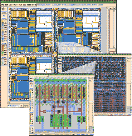
3D-View Zoom In
 

All MAX Layout Tools provide a three-dimensional view.

Micro Magic, Inc.
Fast Silicon Fast    


  • True 3-Dimensional Layout
  • Manages Multiple Tech Files

MAX-3D

The World's First True 3-D Layout Editor


3D chip 3 technologies

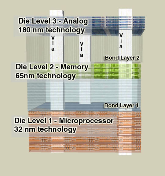
Illustration of three different technologies in three different levels, joined with Through Silicon Vias and bonding layers.

MAX-3D is the only true 3D layout editor, handling multiple technologies with true Through-Silicon Via (TSV) capability.

MAX-3D can handle your largest multi-wafer ID designs -- in the trillions of devices. Even the largest designs redraw in real time.

Enabling 'Through-Silicon Via Wafer Stack' Technology

Through-Si Via Wafer Stacking is a technology allowing faster interconnects between discrete wafers. This is accomplished by connecting wafers of varying technologies together with vias through the wafers yielding a single 3-D stack. For example, a Microprocessor in 32nm technology can be combined with a Memory in 65nm technology and an Analog device in 180 nm technology (see figure above).

The magic behind MAX-3D is the patented technology allowing each individual wafer to use its existing tech file without modification.

MAX-3D has the capacity and speed to handle these large and complex designs. Features such as limiting editing to a single wafer, or connectivity tracing through multiple wafers, make MAX-3D the only editor for your 3D designs.

Your package and chip can be loaded simultaneously.


  • View Any Chip, Any Size, Real Time
  • Integrated Calibre®  Interface
  • Automatic Connectivity Tracing
  • Reads GDSII or OpenAccess Layouts

MAX-View Layout Viewer

MAX-View Layout Viewer - Real-Time Speed and Power

Max-View is the fastest Layout Viewer on the planet. MAX-View can handle the largest IC design databases -- in the trillions of devices

Whether your chip is in OpenAccess, GDSII or native MAX format, MAX_View can display the entire desgin, with all layers on, in real time.

MAX-View reads in layer name, color, and fill pattern information from other industry standard technology files. You can easily customize the colors, stipple patterns, transparency and hot key assignments. True transparency via OpenGL makes it easier to see details on lower levels.

MAX-View Makes It Easy to Explore Your Layout

Push into and pop out of cells, view levels of hierarchy or internals of cells to get the best understanding of your design. Explore hierarchy easily with MAX-View's Cell Hierarchy Browser.

MAX-View's automatic connectivity tracing allows you to easily see how things are connected. No extraction is required.

Invoke Calibre®  with a single click and view the resulting errors directly in MAX-View. Or -- if you prefer -- Calibre®  RVE can interactively display errors in MAX-View.

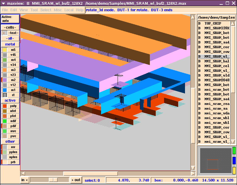
Like all MAX products, to make your display more interesting, MAX-View also privides a 3-dimensional view.


PnR image

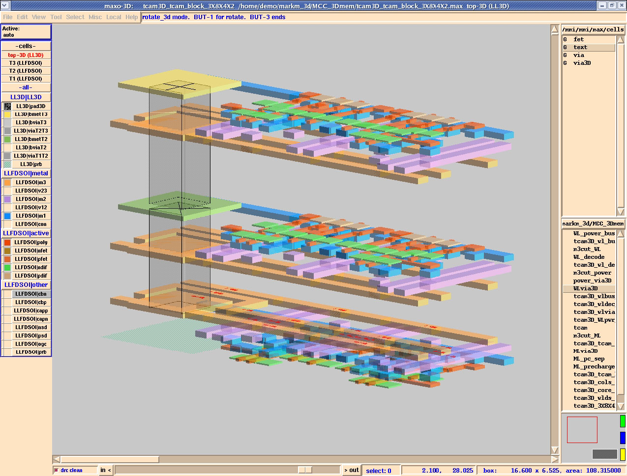
Actual screenshot of MAX-3D Layout Editor - True Through-Silicon Via (TSV) layout and editing using multiple technologies at the same time.


MAX Full Featured Layout
  • Real-Time Interactive DRC and Connectivity Tracing
  • Integrated Calibre®  Interface
  • OpenAccess + IPL Support

MAX - The Intelligent Layout Environment

MAX is much more than a layout tool; it is an intelligent IC layout environment. MAX is equally at home with all aspects of physical deisgn, from creating cells for a library, to interacting with place-and-route activities at the block-level, to assembling an entire chip. Its real-time interactive DRC shows you DRC errors right on the layout!

Powerful enough to handle the largest of chips, yet easy enough to learn that designers can do real work the first day.

View and Edit Entire Chips down to Full-custom Cells

MAX is for Physical Design Teams who need to view, manipulate, and understand what is going on with their place-and-route process.

MAX is for Integration Teams who need to efficiently manipulate large amounts of data during assembly and perform back-end analyses.

MAX has a number of features that make it the best choice for doing IC layout for high-performance, fast time-to-market designs.


  • Schematic-Driven Layout
  • Cross-probing Between Schematic & Layout

MAX-LSchematic-Driven Layout Header

MAX-LS - The Tool for Real Layout Designers

MAX-LS - MAX, plus the power of schematic-driven layout for even faster design.

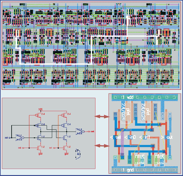
MAX-LS features true Schematic-Driven Layout Design, offering the ability to interactively generate layout that is DRC- and LVS-correct with devices automatically sized.

Based on your schematic, MAX-LS can generate every transistor, show flylines as to how they should be connected, and cross-probe between schematic and layout. This gives the layout designer complete control, yet assures rapicd physical design development.

There are many features for automatic generation of library cells, including power rails, well ties, router pitch, cell height, etc.

A special analog mode preserves schematic placement for better signal integrity.

Real-time connectivity checking ensures your designs are wired correctly.


PnR image

Schematic-driven layout generation, cross-probing between layout and schematic, interactive connectivity tracing and real-time DRC.

 
MMI Logo  
 

MAX Layout Environment Tools Are:

  • FAST AND POWERFUL - 50x faster; Real-Time Redisplay of World's Largest Chips; Real-Time DRC; Schematic-Driven Layout; Generators; API.
  • PRODUCTION PROVEN - Large SoCs to Memories, On Time and Working.
  • FRIENDLY - You Can Do Real Design Work the First Day.
  • OPEN ARCHITECTURE - Open File Formats and OpenAccess Support.
  • CALIBRE® INTERFACE - Means Faster and Easier Error Checking.
  • CUSTOMIZABLE - Tcl/Tk Support and API for Automation and Customization.
  • LOADED WITH FEATURES
    • Real-Time Interactive DRC & Connectivity Tracing.
    • Interactive Wiring Tool with Flylines.
    • All-angle Capability.
    • True Transparent Layers via OpenGL.
    • One-click Calibre®   Interface.
    • Fully Hierarchical Viewing and Editing.
    • Generators for Automated Layout Structures.
    • Smart Palette for Easy Control and Feedback on Layers.
    • Rotational 3-D Viewing.
    • Supports GDSII, ASCII and Other Industry-Standard File Formats.
    • OpenAccess and IPL Support.
    • Complete On-Line Documentation and Tutorial.
    • Available for Linux and Solaris.


MMI Layout Tools Features Comparison Table
  MAX
-View
  MAX   MAX
-LS
MAX
-3D
50X Faster
Full Documentation
Linux & Solaris
Select Net Connectivity
Representational 3D Display
GDSII    1     2    2    2
Groups  
Wire Mode with Automatic Via Insertion  
Bus Routing  
Wire Stretch  
Programmable  
ASCII Database  
Tck/Tk API  
Interactive DRC  
All-Angle Editing  
Flylines      
Cross-Probing      
Schematic-Driven Layout      
3-D Editing      
Concurrent Multiple
Tech Files
     
 
1 Read Only
2 Read/Write


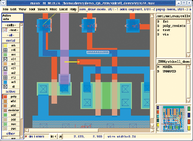
Interactive DRC error

Above, we see that Interactive DRC (block of white dots) is working as the wire is being drawn (yellow cursor line at center of image).

 
MMI Logo
Micro Magic, Inc.
Sunnyvale, CA 94087
Phone: 408.414.7647
www.microgmaic.com
 
Return to Tools Page    View Datasheets in PDF: DPC | MAX + MAX-LS | MAX-3D | MAX-View | MCC | SUE View Datasheets in HTML: DPC | MAX + MAX-LS | MAX-3D | MAX-View | MCC | SUE